Document Source: War Department, War General Staff, Organization and Training Division G-3, Washington DC. Subject: Manual on Weapons for Jungle Warfare. The enclosed manual which was prepared due to a special mission by Gen W. A. Borden should be of general interest. This should be called especially to Maj Link’s attention as it contains information he requested me to get for him. Attention is called to a recent change in the text. The mount referred to is no longer of the same general type as the mount T9, as the test has shown that the 81-MM base plate is not heavy enough for the job. (Transcribed and Illustrated by Doc Snafu)
FOREWORD
Operations against the Japanese in the Pacific Theaters have demonstrated the urgent need for methods of destroying or dispersing their infantry employed in the jungle without the delays and difficulties now encountered. On August 30, 1943, Col W. A. Borden was detailed in a special mission by the Chief of Staff relative to the development of weapons for jungle warfare. After establishing procedures to be followed and directing the development and procurement of certain equipment, he, with a group of five other officers, proceeded by air to SWPA and SPA to demonstrate the new items being proposed and to ascertain the views and requirements of the combat organizations. Col S. B. Ritchie was designated to act for Col Borden in his absence.
A study was made promptly of the types of bunkers used by the Japanese. Replicas were constructed at Aberdeen Proving Ground, Edgewood Arsenal, Fort Belvoir, Fort Pierce, Fort Bragg, Fort Benning, and near Ocala, Florida. For the latter, the Army Air Forces have selected a terrain that nearly duplicates jungle terrain as could be found in this country. It is expected that, in addition to tests by the Air Forces, combined tests may be conducted in this area later. One of the difficult problems in jungle warfare is locating bunkers and other enemy positions without suffering undue casualties. The development of instrumental and other means to facilitate the location of the enemy in the jungle is being pursued vigorously.
Testing of standard equipment to determine its effectiveness against personnel in foxholes and in destroying bunkers and to establish desirable modifications in this equipment has gone forward as rapidly as possible along with the development and test of new items. This development work is still in progress and should terminate in the standardization through an established military procedure of equipment found suitable and desirable, and manufacture and issue of the items with appropriate technical and tactical doctrines. The use of standard weapons with increased firepower is stressed. Where improvements are made in existing equipment or where new items are introduced, maximum utilization is made of standard components readily available to simplify procurement and save time. To withstand the peculiar weather conditions, more effective packaging and crating are being developed. Aerial delivery containers for safe and effective transport and delivery of jungle warfare items by air within the theaters are included in the program. The imperative need to keep weights to an absolute minimum for man-packing is emphasized.
Reports from Col Borden’s mission indicate that many of the items which have been proposed are desired, and requisitions have already been received for most items submitted for test. Initial shipments to the Pacific Theaters have started. It is expected that a number of the items found suitable for jungle warfare will also have useful applications in other theaters. There follows a brief description of the items under consideration and the development projects underway. All agencies concerned have cooperated fully in making this undertaking a success.
S. B. Ritchie
Colonel, Ordnance Department
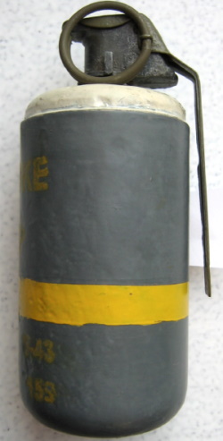
This hand grenade is designed for laying smoke screens, and for incapacitating enemy personnel by means of severe and slow healing burns caused by the white phosphorous filler of the grenade. The M-15 grenade is cylindrical in shape. It is 4.5 inches high, with a diameter of 2 3/8 inches. It consists essentially of a grenade body, a burster well, and a Fuze, Detonating, Hand Grenade, M-6A3.
Note: having found hundreds of WP M-15s in the EU battlefields of Belgium, Holland, France, and Germany, the M-15 is known to have been manufactured with four different body shapes. Getting hit with WP while emptying this grenade, the only way to stop the WP burn your hand is to bury it in the ground or in the sand. Water doesn’t work because the WP keeps burning. I’ve tried it twice and this hurts a lot for several seconds. (Doc Snafu)
PRINCIPAL CHARACTERISTICS
Height 4.5 ins.
Diameter 2 3/8 ins.
Weight empty 9 ozs.
Weight loaded 24 ozs.
Weight of WP filler 15 ozs.
Hand Range 30 to 40 yds.
Rifle Range op to 80 yds.
Duration of screen 25 sec.
The radius of the burst is 20 ft.
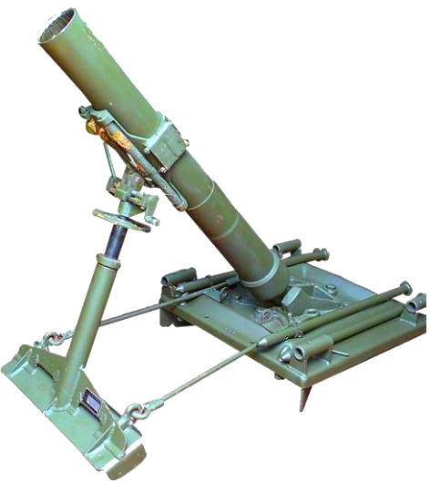 MORTAR, CHEMICAL, 4.2 INCH, M-2A2
The 4.2 Inch Chemical Mortar is a rifled, muzzle-loading weapon. It can deliver high explosive shells by plunging fire with a demolition effect that is destructive to bunkers and field fortifications. It also utilizes a chemical shell to lay smoke screens and HE Shell with time fuze against personnel. Firing may be conducted at elevations of between 800 mils and 1080 mils, with a right and left traverse of 150 mils each. The Mortar, M-2A2, consists of a barrel with a firing mechanism and shock absorbing mechanism; a base plate equipped with collapsible (sliding) carrying handles on two sides, and a standard that supports the barrel when the weapon is in firing position. The standard is composed of a traversing mechanism, elevating screw, elevating wheel, shock absorber, spades, and connecting rods which fasten the standard spade parts to the base plate. The mortar may be broken down and transported on a two-wheeled hand cart drawn by either two or four men, depending on the terrain; carried manually by its crew, or packed on mules. The weapon disassembles into three loads, consisting of the barrel, the base plate, and the standard.
PRINCIPAL CHARACTERISTICS
Weight of barrel 100 lbs.
Weight of base plate 150 lbs.
Weight of standard 53 lbs.
Total 305 lbs.
Elevation 800 mils to 1080 mils.
Traverse (total) 500.mils
Maximum range 3200 yds to 4400 yds.
Minimum range 600 yards
Rate of fire-rapid. 20 rds. per minute
Rate of fire-sustained 5 rounds per minute
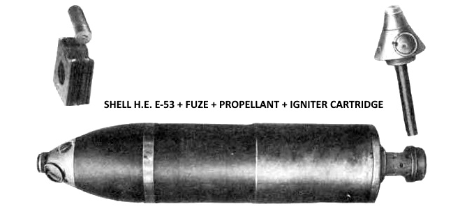
SHELL HE 4.2″ CHEMICAL MORTAR E-53
This shell is for use in the 4.2″ Chemical Mortar, M-2A2. It is a streamlined projectile of the semi-fixed type. It is extremely effective against bunkers, pillboxes, and other defense structures utilized in jungle warfare. The E-53 shell consists essentially of a shell body, a fuze, a TNT bursting charge, and a propelling charge composed of an ignition cartridge and a number of bundles of powder serving as the propellant. A point detonating instantaneous fuze, a time fuze, or a delay fuze can be employed with this shell. The external dimensions of the E-53 shell are the same as those of the standard 4.2″ Shell, M-3. The wall thickness of the E-53 Shell is, however, .43″ as compared to .225″ for the M-3. The weight of the Shell, E-53, empty, is 25.7 pounds, when loaded
with its charge of 6.3 pounds of TNT filler, it weighs 32 pounds.
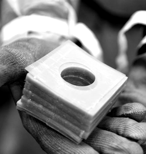 CHARGE PROPELLING 4.2″ CHEMICAL MORTAR E-5
This charge consists of 20.5 bundles or increments. Each bundle is composed of two 60-grain, 2 3/4″ square sheets of .025-inch Ballistite. The 20.5 separate bundles are assembled as follows: five 1-bundle packets, three 5-bundle packets, and one 0.5-bundle sheet. The charge therefore actually comprises but three kinds of packets and nine pieces. The kinds may be clearly identified by their thickness and stitching. Using the subject charge, it is possible to fire the E-53 shell to a maximum range of approximately 3500 yards.
FUZE T & SQ E-39 FOR SHELL HE 4.2″ M-3
The E-39 Fuze is a combination of super-quick and 25-second-powder-train time fuze normally used with the 75-MM gun and howitzer and the 105-MM howitzer. The employment of a special adapter booster with this fuze makes it function efficiently with the Shell, HE 4.2″ M-3, for time action or for super-quick detonation on impact. The fuze consists of a closing-cap assembly, which carries the super-quick element; a concussion plunger for initiating the burning of the time train; a body that carries two brass time-train rings; an interrupter, and a black powder magazine charge. The rear portion of the body is threaded for assembly to the mating threads of the booster.
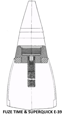 The time-train ring is graduated from 0 to 25 seconds, the graduations from 1 to 25 being in a division of 0.2 seconds. Safety features of the fuze include a firing pin support that will collapse only under the force of impact and supports the firing pin at a safe distance from the detonator assembly; an interrupter that prevents super-quick action in the event that the super-quick detonator functions prematurely; a removable cotter pin which supports the plunger during transportation, thereby, preventing the firing of the concussion primer through accidental shearing of the shear pins; plunger shear pins which restrain movement of the plunger after removal of the cotter pin until the shear pins are sewed as a result of set-back which enables both times rings to burn completely without igniting the base charge of the fuze; vent closing disks which prevent premature ignition of powder trains by chamber gases and seal them against moisture and a safety disk at the ignition end of the graduated-ring time train which, when the fuze is set at less than O.4 second covers the body pellet and prevents its ignition by the graduated ring.
There is no selective setting provided for super-quick action, but, when desired, it is obtained by firing with the time train set at safe or with a time of burning which is surely in excess of the time of flight. When fired for super-quick action, the nose of the fuze must impact on hard ground to insure functioning in the first and second zones. In the outer zone, the fuze will function dependably on all types of ground or water impact. The adapter-booster is an assembly of a special aluminum adapter, lower detonator assembly of the Fuze, PD (Point Detonating), M-46 or M-47, and the booster from the CWS 4.2″ CM Fuze, M-3. By means of this adapter – booster the E-39 T and SQ Fuze can be assembled to the M-3, HE, 4.2″. CM shell without modification of fuze, shell or loading. These items are separate and are not issued as components of a complete round.
This fuze is an impact type (PD – Point Detonating), single purpose, delayed action point detonating fuze similar in function to the M-53 fuze used in the 81-MM Mortar. It is intended for use with the M-3 HE 4.2″ Chemical Mortar Shell for producing a demolition effect by the detonation of the HE charge after the projectile has penetrated the target. The delay interval between impact and detonation is .10 seconds. It is designed to be bore-safe and to function on impact with the ground or water when fired in any zone of the 4.2″ Chemical Mortar. The fuze is a component of the complete rounds and not a separate item of issue. The fuze consists of the body, containing the booster, the slide assembly, and detonator, and the slider locking device; the head, which contains the firing pin and the delay element; and the delay element with a primer, delay charge, and a ‘spitter’ charge for firing the detonator in the slider.
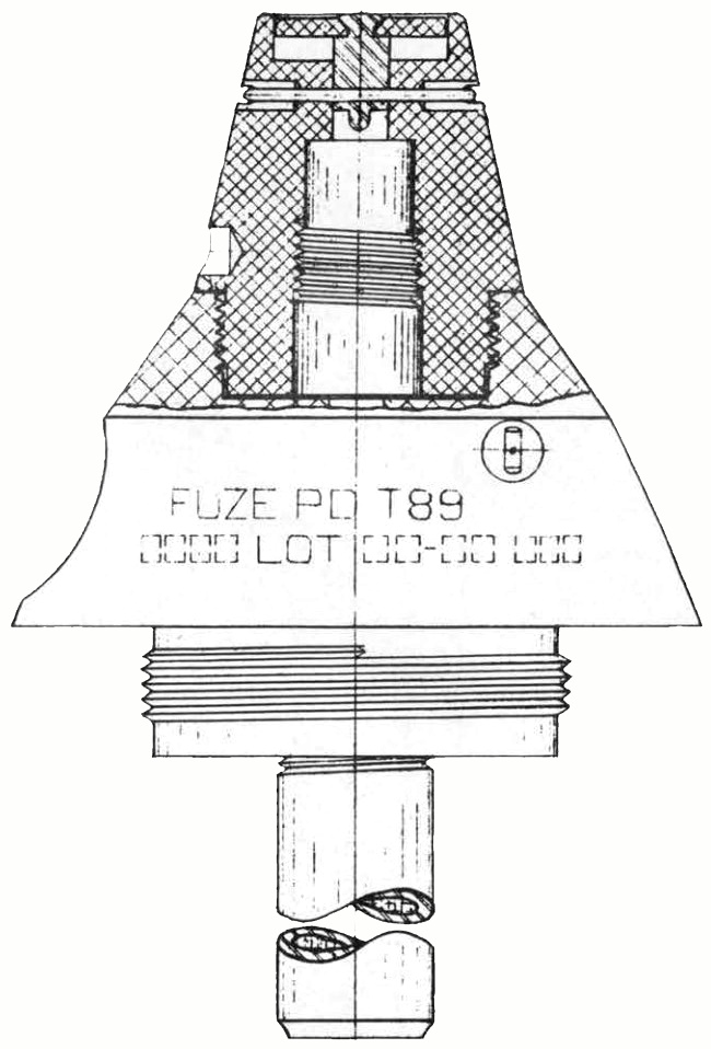 The firing pin is normally held rigidly in place by a shear wire in the nose of the fuze with the front of the pin a short distance above the primer in the delay element. The delay element is screwed into the fuze head so that the ‘spitter’ charge lies directly above the position occupied by the detonator when the slider is in the armed position. The detonator is out of line with the delay element in the unarmed position, but, when the fuze is armed it occupies a position in line with the delay element and the booster. Safety devices comprise the shear wire, which prevents motion of the firing pin towards the primer until a force equivalent to impact with a firing target has been applied to the nose of the fuze, and the positioning of the detonator out-of-line with the booster charge until the fuze has been armed, thus preventing the functioning of the booster by chance action of the detonator. As further precautions, the slider is locked in place by a cotter pin and a set-back pin, and centrifugal force is required to arm the slider. Upon impact, the nose of the fuze is crushed and the firing pin is forced down, severing the shear wire and finally contacting the primer in the delay element. The primer ignites the delay charge which, after burning for 0.10 seconds, ignites the ‘spitter’ charge. A flame from the ‘spitter’ charge is directed downward onto the detonator. The detonator then explodes and detonates the booster charge which, in turn, detonates the high explosive filling in the shell.
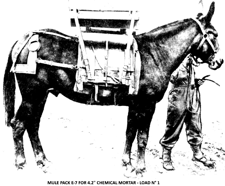
PACK MULE E-7 FOR 4.2 INCH CHEMICAL MORTAR
Animal transport of the 4.2″ Chemical Mortar is practicable by means of mules equipped with packs. The pack consists of the Saddle, Phillips, Pack, and Cargo, to which have been welded with strap metal adapters and hangers to accommodate the disassembled mortar with its ammunition, tools, and accessories. The mortar is divided into two loads for transport, each load to contain the following items:
Load No. 1
Baseplate 159 lbs
Shell HE 4.2″ (2 rds) 49 lbs
Adapters and Hangers 15 lbs
Total: 223 lbs
Load No. 2
Barrel 101 lbs
Standard 52 lbs
Tools and Accessories 75.5 lbs
Total: 228.5 lbs


